ControlBoard
The control board is a shield for an Arduino Mega 2560. It is responsible for:
- communication with the computer (over USB)
- impedance-measurement (estimating drop position, velocity, etc.)
- control of other system hardware (Signal Generator Board, High-Voltage Switching Board, Extension Module Proto Board)
.jpg)
.jpg)
To improve the accuracy of impedance/capacitance measurements, we recommend installing an Anti-Aliasing Filter Shield.
The control board software consists of 2 components:
- Arduino firmware
- C++ software that runs on a computer (accessible through a Python API) for communicating with the Arduino
In addition, there is a
plugin which provides an interface to the Control Board for the
Microdrop application.
You can install the latest version of the plugin within
Microdrop by selecting
the menu item File/Manage plugins. Click on the Download plugin...
button and choose it from the list. This will automatically trigger
installation of the appropriate firmware.
You can download the KiCAD designs for the control board here

The control board has 9 jumpers which allow it to be operate in different system configurations (e.g., no power supply, Arduino Due as a replacement for the Arduino Mega 2560 ). By default (i.e., using a power supply and Arduino Mega 2560), you should set the jumpers to match the image above. Details for each of the jumpers are given below.
Jumpers JP1 and JP2 set the power source for the +5V and the
+3.3V power that is supplied over the power bus (e.g., to the
SignalGeneratorBoard). These voltages can be connected to either the
Arduino’s voltage regulators or the !DropBot’s power supply. In most
cases, these jumpers should be set to supply voltages from the PSU, but
it is possible to make a minimal system that doesn’t require a power
supply.
Jumpers JP3-JP9 set the voltage level on the communication bus (VCC,
i2c, and SPI). By default, these signals operate at +5V; however,
these jumpers make it possible to use the
Arduino Due (which
operates at +3.3V) in place of the
Arduino Mega 2560.
In order to compile the C++ code, it is recommended that you first setup the ‘’Microdrop’’ development environment as described here. In addition, you will also need to install some dependencies by following the instructions for Windows or Linux.
All of the development files are tracked in a git repository. Assuming that you have git installed on your computer, you can download the latest version of the source code by going to a command line and typing the command:
git clone –recursive https://github.com/wheeler-microfluidics/dmf-control-board-firmware
Assuming that everything is setup correctly, you should be able to build
the software by running the command scons.
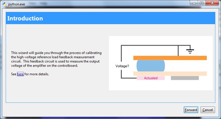
The Control Board implements closed-loop control of the electrode actuation voltage. This is achieved by measuring the voltage output by the amplifier, and using the measured value to dynamically adjust the low-voltage output of the Signal Generator Board until the desired high-voltage output is reached.
To measure the high-voltage signal from the amplifier, the Control Board includes attenuation circuitry to reduce the high-voltage signal to a level that is within the input range of the ADC of the Arduino (0-5 V). The attenuation circuit includes a bank of several reference resistors, where a particular resistor is selected based on (1) the amplitude, and (2) the frequency, of the high-voltage signal. The higher the output-voltage of the amplifier, the lower the required resistor impedance necessary to attenuate the high-voltage signal to within the range of the ADC. While a sufficiently small resistor could be used to attenuate any high-voltage signal, selecting the largest reference resistor that does not saturate the ADC maximizes the signal-to-noise ratio.
Between DropBot builds, there are several components that may cause slight variations in system characteristics. In the case of the high-voltage attenuation circuitry on the control board, the most significant sources of variation are the reference resistor values and the associated parasitic capacitance of each resistor. To compensate for these variations, it is necessary to calibrate the ControlBoard to match the actual resistance and parasitic capacitance values of the attenuation circuitry.
- Launch the Microdrop application.
- (optional)If this is not the first time calibrating the
DropBot, you may want to reset the calibration values to ensure
appropriate initial conditions for the fitting process used during
calibration. To reset the calibration to defaults, select the menu item
Tools/DMF control board/Configuration/Reset to default values. - Select the menu item
Tools/DMF control board/Calibration/Calibrate reference load. - Connect an oscilloscope to the output of the amplifier following the
wizard’s instructions.
- Select the calibration frequencies (or accept the
defaults).
- Follow the prompts of the calibration wizard,
entering the AC RMS voltage measured by the oscilloscope at each step.
- Verify that the calibration fits look
reasonable. If so, click
Apply. - (optional) Now that you’ve calibrated the
reference load, you may wish to enable auto-amplifier-gain adjustment.
From the menu, select
Tools/DMF control board/Configuration/Edit settings, and click on theAuto_adjust_amplifier_gaincheck box.


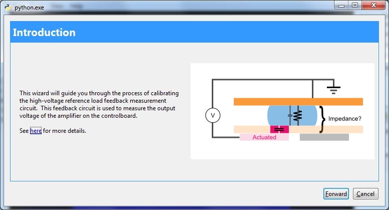
The device load circuit measures the impedance between all actuated electrodes and the top plate. These measurements are used to estimate the location of drops on the devices and to determine their velocity. Impedance is inversely proportional to the volume of liquid between the actuated electrodes and the top plate.
- Launch the Microdrop application.
- (optional)Install the Anti-Aliasing Filter Shield and verify that it is enabled.
- Select the menu item
Tools/DMF control board/Calibration/Calibrate device load. - Connect the TestBoard to the DropBot following the wizard’s
instructions, i.e.,
- Connect the DropBot
Out to Ampto the amplifier input. - Connect the amplifier output to !DropBot
In from Amp. - Connect the HV signal cable for !DropBot channels
0-39to the TestBoard. - Clip the
redalligator clip on the feedback cable to the TestBoard’s ground pad.
- Connect the DropBot
- Select the calibration frequencies (or accept the
defaults).
- The system will perform a series of measurements
across a range of frequencies and capacitance values. This can take
several minutes.
- Verify that the RMSE, CV and bias look
reasonable. If so, click
Apply. The following images show some typical results with and without the Anti-Aliasing Filter Shield, respectively.


.jpg)