A standalone ultrasonic distance meter built around the MSP430G2553, an HC-SR04 ultrasonic sensor, and an I2C 16x2 LCD, with a potentiometer-controlled, PWM-dimmed LED brightness indicator. Designed and built as a PCB for EEL3926 Junior Design.
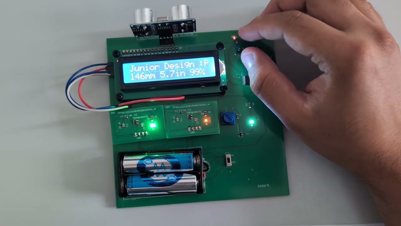

The board triggers the HC-SR04 sensor, times the returned echo pulse using a hardware timer/interrupt combo, converts that time into a distance, and prints the live reading to a 16x2 character LCD over I2C. A potentiometer feeds the on-board ADC and sets the duty cycle of a software-PWM signal that drives an indicator LED, while a second LED (driven through an N-channel MOSFET) blinks once per measurement cycle as a heartbeat indicator.
Every ~600 ms the device:
- Fires a 10 µs trigger pulse on the HC-SR04.
- Waits for the sensor's echo pulse and times its width using a Timer A interrupt (10 µs resolution) plus a Port 2 rising/falling-edge interrupt.
- Converts the elapsed time into distance (mm and inches).
- Samples the potentiometer with the 10-bit ADC and updates the LED PWM duty cycle.
- Formats and writes
"<mm>mm <in>.<in>in <duty>%"to the LCD's second line.
- Real-time distance readout in millimeters and inches, updated twice a second
- Duty cycle 0–100% brightness control of an indicator LED via a potentiometer
- I2C-driven 16x2 LCD (PCF8574-style backpack, default address
0x27, HD44780 4-bit protocol) - Interrupt-driven echo timing for consistent, accurate measurements (no busy-wait polling of the echo line)
- Custom boost-converter regulator board to supply a clean, stable rail from battery power
- Fully custom two-board PCB design (main sensor/MCU board + boost regulator board)
| Component | Part / Notes |
|---|---|
| MCU | Texas Instruments MSP430G2553 (20-pin TSSOP), 8 MHz DCO |
| Ultrasonic sensor | HC-SR04 (4-pin: VCC, TRIG, ECHO, GND) |
| Display | 16x2 character LCD with I2C backpack (HD44780 controller, default I2C address 0x27) |
| Brightness control | Potentiometer into ADC10 channel A1 (INCH_1) |
| Indicators | 2x LED — one PWM-dimmed via ADC/duty cycle, one MOSFET-switched heartbeat blink (BS170 N-channel MOSFET) |
| Power | Battery input through two TPS61322 boost regulators — one fixed at 3.3V (MCU/logic rail), one fixed at 5V (LCD/HC-SR04 rail) |
| Misc | Power switch, pull-up/pull-down resistors, decoupling caps |
| Signal | MSP430 Pin | Definition |
|---|---|---|
| I2C SCL (to LCD) | P1.6 | LCD_SCL |
| I2C SDA (to LCD) | P1.7 | LCD_SDA |
| HC-SR04 Trigger | P2.1 | USENSOR_TRIGGER |
| HC-SR04 Echo (interrupt) | P2.2 | ECHO_INTERUPT |
| Potentiometer input (ADC) | P1.1 / INCH_1 |
ADC_INPUTPIN / ADC_INPUT |
| PWM LED output | P1.2 | ADC_LED |
| Heartbeat LED (MOSFET gate driver) | P1.5 | BIT5 |
Note: P1.6 has a default on-board LED on many MSP430 LaunchPad/experimenter boards — it must be removed/disconnected if that pin is reused for I2C SCL.
Boards were designed in Autodesk Fusion 360 (Electronics workspace).
Main board schematic — MSP430G2553, HC-SR04 header, I2C LCD header, potentiometer, LEDs, and power switch/battery input:

Main board PCB layout:
Boost regulator schematic — TPS61322 boost converter stepping battery voltage up to a regulated output rail:

Boost regulator PCB layout:


Init_HW()— stops the watchdog, sets the DCO to 8 MHz, configures Port 1/2 directions, and brings up I2C, both timers, and the ADC.- Timer A0 (10 µs tick) — drives the microsecond-resolution delay function (
Delay_Timer) and increments the free-running counter used to time the ultrasonic echo pulse. - Timer A1 (100 µs tick) — implements a software PWM with a 10 ms period, toggling the indicator LED on/off based on the
Dutyvariable (0–100). - Port 2 ISR — captures the timestamp of the echo pulse's rising edge; the falling edge is detected in the Timer A0 ISR, and the difference between the two gives the pulse width.
Ultrasonic_Trigger()/Ultrasonic_Echo_Read()— fire the 10 µs trigger pulse and return the measured echo time (in 10 µs units), whichmain()converts to mm/inches using the speed of sound (340 m/s, double path).- LCD driver — bit-bangs the HD44780 4-bit protocol over the hardware I2C module (
UCB0), toggling the RS/RW/E/backlight lines through the I2C expander.
Timing resolution is configurable via TIMER_MAX_COUNT_A in the header — the current setting (10 µs/tick) gives roughly 3.4 mm double-path resolution (~1.7 mm single path).
This project targets Code Composer Studio (CCS) with the MSP430 toolchain.
- Create a new MSP430 project in CCS targeting the MSP430G2553.
- Add
main.candJunior_Design.hto the project. - Build and flash over Spy-Bi-Wire (SBWTDIO/SBWTCK, pins 16/17) using a LaunchPad or standalone programmer.
- Power the board (battery + boost regulator, or a regulated 3.3V/5V bench supply) and observe the LCD.
- Power on — the LCD displays
Junior Design :Pon line 1. - Line 2 updates continuously with the live reading, e.g.:
152mm 5.9in 63% - Turning the potentiometer changes the LED brightness (duty cycle shown as a percentage on the LCD).
- The heartbeat LED on P1.5 toggles once per measurement cycle to confirm the loop is running.
- Written for EEL3926 Junior Design.
- The I2C LCD driver portion is adapted from a public MSP430F5529 I2C/LCD1602 interface example (credited in
Junior_Design.h); used here for educational purposes. - Claude 5 Sonnet for drafting the README.md file
This project is MIT-licensed — see LICENSE — with one exception: firmware/Junior_Design.h was written by Dr. R. Weeks for educational use only and is not licensed for commercial use. See THIRD_PARTY_NOTICES.md for details.